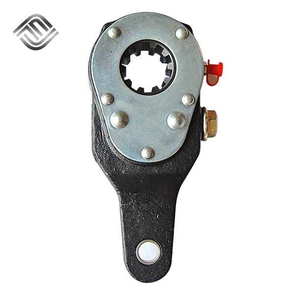
Brakes are often referred to as brakes, and their funct […]
Brakes are often referred to as brakes, and their function can quickly stop the running mechanical parts and slow down the speed of the mechanical parts. Some brakes are also equipped with automatic adjustment devices for brake clearance. In order to reduce the braking torque and structural size, the brake is usually installed on the high-speed shaft of the equipment, but large equipment with high safety requirements should be installed on the low-speed shaft close to the working part of the equipment. Some brakes already have a very professional scale and have been researched and used by most manufacturers.
The brake is a friction disc brake that is spring-loaded in the event of a sudden power failure. It can be matched with electric motors to form a new type of braking motor, and can also be used in mechanical transmission systems to achieve fast parking and accurate positioning, and can be used in situations such as safe braking when power is off. This kind of brake has the advantages of simple structure, wide adaptability, low noise and reliable braking. It is widely used in various mechanical transmission devices. It is an ideal executive element in industrial modernization. The characteristics of Wholesale automatic slack adjuster the brake itself have been widely used.
How to Adjust Hydraulic Push Rod Brakes
There is a long screw rod above the brake, the two ends are respectively located above the two brake shoes, and one end is also connected to the pusher through some lever mechanisms. A relatively simple adjustment method is to power off the motor that needs to be braked (remove the wiring in the motor junction box, but at the same time pay attention to the complete release of the brake during the adjustment process), only...
The hydraulic principle of hydraulic push rod?
You are a dedicated driver without a license to operate. Before taking up a job, a new driver must pass the training and assessment organized by the Equipment Office.
Adjustment of Electro-hydraulic Block Brake
1. Adjustment of tile setback
Adjusting the backing distance of the pad is actually adjusting the stroke of the pusher. In the brake shown in FIG. 1 , loosen the locknut 11 and tighten the brake lever 10 clockwise to increase the compensation stroke of the pusher, and vice versa to decrease the compensation stroke of the pusher. Adjust the compensation stroke hc to the specified value. If the compensation stroke of the pusher is adjusted too large, it is necessary to unscrew the compensation fixing bolt 7 and take out the compensation sleeve. At this time, the pin is not hindered by the triangular plate and can rotate freely counterclockwise. At this time, the brake lever can be loosened counterclockwise, and finally restored, and the compensation stroke and automatic compensation device can be readjusted.
2. Adjustment of tile setback distance evenly
The tile back-off equalizing device generally does not need to be adjusted, and only needs to be adjusted after the initial or re-installation. The method is to manually or electrically open the brake and observe the left and right pads retreat. If the setback of the right pad is larger than the setback of the left pad, loosen the set nut on the left and turn the adjusting bolt clockwise (or loosen the set nut on the right and turn the adjusting bolt counterclockwise), observe the left and right Changes in tile setback. If not, continue until they are equal. The equalizing lever should be roughly horizontal, otherwise, the position of the brake base needs to be moved so that the center line of the brake roughly coincides with the center line of the brake wheel.
3. Adjustment of braking torque
The adjustment of the braking torque is very simple, just adjust the torque nut. In general, using a wrench to turn the torque adjustment nut clockwise shortens the length of the spring and increases the braking torque, and vice versa. The length of the spring should not exceed the upper and lower lines on the moment scale, otherwise, the spring may be damaged, the brake may fail to work, or even cause a safety accident!
4. Adjustment of automatic compensation device for brake pad wear
(1) Press down the pin of the compensation device to the top (contact with the lower surface of the inner ring of the compensation sleeve).
(2) Loosen the set bolt until its lower end face is outside the inner ring of the compensation sleeve.
(3) Manually or automatically lift the pusher push rod, and the dial pin is brought up at this time. Then manually release or power off the pusher, so that the push rod is reset under the action of the brake spring, and the position of the dial pin will be pressed down a little at this time.
(4) Tighten the set bolt downward until its lower end face is basically in contact with the dial pin, and then tighten the set nut.
normal working conditions
Ambient temperature -20℃~40℃;
The complete relative humidity is not more than 90%;
In a medium without explosion hazard, and in an environment without sufficient gas and conductive dust to corrode and destroy insulation;
The altitude of the installation site conforms to the GB755-87 standard, and is suitable for three-phase 380V, 50Hz AC power supply.
Increase the strength of the brake disc
Copyright 2018-2024 © Shaoxing Fangjie Auto Parts Co., Ltd. All Right Resrrved. Technical Support : HWAQ OEM/ODM Heavy Duty Truck Brake Parts Suppliers